3D printing & STL5 min read
How to reduce STL file size without ruining the print
Why STL files get large, how to read the triangle count straight from the file size, and what binary, re-export, decimation and 3MF each save in practice.
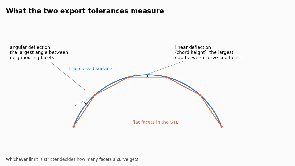
Two tolerances decide how smooth a STEP file comes out as STL: the largest gap between facet and true surface, and the largest angle between neighbouring facets. For FDM, 0.05 mm and about 11° is enough; finer settings mostly add file size.
Checked on 1 October 2026. The definitions below come from the Open CASCADE, FreeCAD, Autodesk Fusion and SOLIDWORKS documentation; the file sizes come from converting one sample part ourselves.
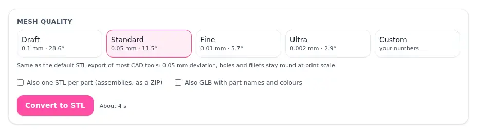
A STEP file stores exact curved surfaces; an STL stores only flat triangles. Converting one to the other means choosing how closely the triangles must follow the curves, and two numbers control that: the linear deflection (how far a facet may sit from the true surface, in millimetres) and the angular deflection (how sharply neighbouring facets may meet, in degrees). For FDM printing, 0.05 mm and about 11° keeps holes and fillets round at print scale without bloating the file. The STEP to STL converter with presets and custom tolerances uses exactly those two numbers, so you can see the effect before you download.
The Open CASCADE meshing guide defines them this way: linear deflection limits the distance between a curve and its tessellation, and angular deflection limits the angle between subsequent segments. Every CAD program has the same pair under its own names. In FreeCAD they appear when you create a mesh from a shape, in Autodesk Fusion under the 3D Print refinement settings, in SOLIDWORKS among the STL export options, and in Open CASCADE, the geometry kernel the Omnvert converter uses, as the two meshing parameters:
| Software | Distance, then angle |
|---|---|
| FreeCAD | Surface deviation, Angular deviation |
| Fusion | Surface Deviation, Normal Deviation |
| SOLIDWORKS | Deviation, Angle |
| OCCT, Omnvert | Linear deflection, Angular deflection |
Sources: the FreeCAD wiki page on Mesh from shape, Autodesk's 3D Print refinement settings and the SOLIDWORKS help page on STL export options.
Which tolerance wins depends on the radius. Worked out from the geometry for a full circle, here is how many segments each preset asks for on a 5 mm hole, a 20 mm boss and a 100 mm cylinder (diameters in mm; Draft is 0.1 mm and 28.6°, Standard 0.05 mm and 11.5°, Fine 0.01 mm and 5.7°):
| Preset | Ø 5 | Ø 20 | Ø 100 |
|---|---|---|---|
| Draft | 13 | 23 | 50 |
| Standard | 32 | 32 | 71 |
| Fine | 64 | 71 | 158 |
On small holes the angle decides: with 11.5° a 5 mm hole gets 32 segments even though 16 would already meet the 0.05 mm distance. On large cylinders the distance decides, because a fixed angle on a big radius leaves a wide gap. That is why setting only one of the two gives either faceted small holes or oversized large parts. The OCCT guide also notes that angular deflection can use a generic default, while linear deflection has an absolute meaning and should match your model.
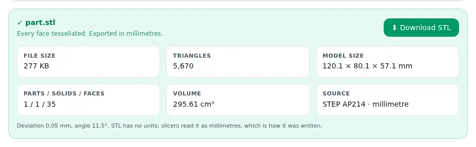
We converted one sample part, a 120 × 80 × 57 mm block with 18 cylindrical and 9 spherical faces, at each preset. The volume was the same every time; the triangle count and file size were not.
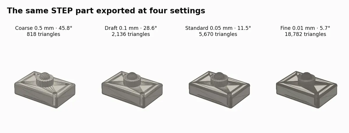
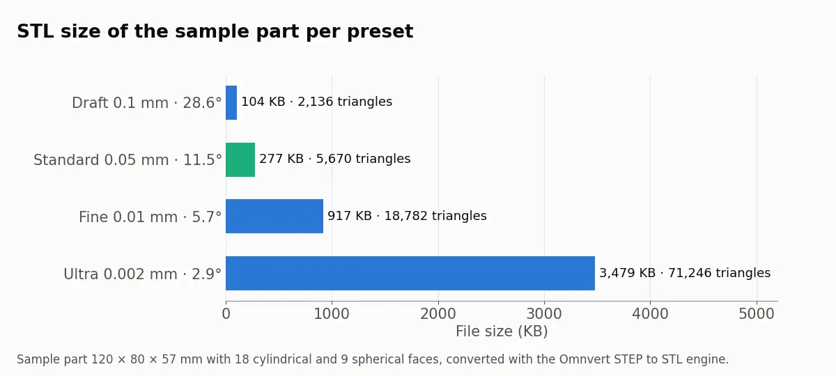
A 0.4 mm nozzle laying 0.2 mm layers cannot show a 0.01 mm difference, so Fine and Ultra mostly cost slicing time and disk space on FDM. Resin printers with 0.05 mm layers and small pixels are where Fine starts to earn its size. Size also matters when you share: this part is 277 KB at Standard and 3.4 MB at Ultra, and on an assembly with dozens of parts that gap reaches tens of megabytes, enough to hit an upload limit; see STL upload limits for that case. Our tutorial on polygon count and print quality covers the same trade-off from the mesh side.
To try your own part, convert the STEP file to STL here, start at Standard and step up only if a curve looks faceted in the preview of your slicer.
STEP files record their unit; STL files do not. Slicers assume millimetres. If a CAD program exports an STL in inches, the part arrives 25.4 times too small. The Omnvert converter reads the unit from the STEP file and always writes millimetres, and the result line shows the source unit so you can confirm it. If you export STL from your CAD program directly, set the export unit to millimetres. The tutorial on scaling in STL shows how to spot a wrong unit.
An assembly exported as a single STL becomes several shells in one file. Where parts touch or overlap, the shells intersect, and slicers handle that differently: Cura merges overlapping volumes by default, others warn. For printing, one STL per part is cleaner, because each part can get its own orientation and settings. For sharing an assembly as one file with its parts intact, 3MF is the better container; see STL vs 3MF vs OBJ.
A finer tolerance cannot recover detail the CAD model never had, and it cannot fix a broken model; if some faces cannot be meshed even after healing, the converter says how many. Each preset also has a ceiling on triangle count, so Ultra on a very large assembly can stop with an error rather than produce a file nobody can slice. If you end up with an STL that is too heavy anyway, the STL reducer brings it down to a target size, and our article on reducing STL file size explains when re-exporting beats decimating.
For FDM printing with a 0.4 mm nozzle, a linear deflection of 0.05 mm and an angular deflection of about 11° keeps holes and fillets round. For resin printers or very small parts, 0.01 mm and about 6° is worth the larger file.
It is the same thing as linear deflection or surface deviation: the largest distance between the true curved surface and the flat facet that replaces it, measured in the middle of the facet.
On a small radius a tiny deviation is reached with few segments, so the angle limit has to do the work. If small holes look polygonal, lower the angle rather than the deviation.
STL has no unit and slicers read millimetres. A file written in inches arrives 25.4 times too small. The Omnvert converter always writes millimetres and shows the unit of the source STEP file.
For printing, one STL per part is usually better because each part can be oriented and sliced on its own. For sharing a whole assembly in one file, 3MF keeps the parts separate inside it.
Why STL files get large, how to read the triangle count straight from the file size, and what binary, re-export, decimation and 3MF each save in practice.
What each format really stores, how many bytes the same mesh costs in all three, why units decide most arguments, and the edge cases that break silently.
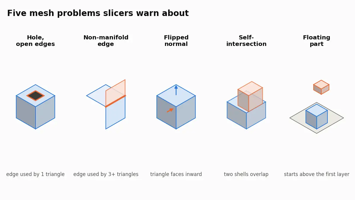
What PrusaSlicer, Bambu Studio and Cura mean by open edges, non-manifold edges, reversed faces and floating parts, and how to repair the STL behind them.